DIY Dual 36 V / 6 A Bench Supply With PC Control (Modbus)
This is a two-channel, PC-controlled lab supply built around XY-SK120X style buck-boost modules (often sold as SK120X-family boards), an ESP32 as a USB serial-to-Modbus RTU bridge over RS-485, and a lot of scrap-bin power engineering: an old transformer, bridge rectifiers, a 5 V rail for logic, and patience with the soldering iron. It is not a Keysight. It is not quiet because someone else designed the fan curve. It is yours, scriptable, and cheap enough that you stop treating the bench like a museum.
Why I Did Not Buy Another “Big Box” Supply
Older Agilent-era units can be mechanically and electrically excellent, but many are noisy in a small lab: the cooling fan runs often and loudly enough that long sessions with a microphone or a headache become the norm. New Keysight (and similar) programmable supplies are superb—and priced accordingly. For repeatable bring-up, burn-in, and scripted tests from a PC, I wanted remote set/read of voltage and current without paying flagship money.
This project is the compromise: two independent channels (Modbus slave IDs 1 and 2), ~36 V / 6 A per module in hardware terms, and a text serial protocol on the USB side so Python, shell scripts, or a small GUI can drive the bench. Same class of workflow as a pro supply for many tasks; different class of specs, noise, and support.
What You Are Building (At a Glance)
| Piece | Role |
|---|---|
| 2× XY-SK120X / SK120X-class modules | Each channel: regulated output, CC/CV behavior per module firmware |
| ESP32 (here: super mini for space; ESP32 devkit preferred if you need dual-core headroom) | USB serial command parser → Modbus RTU on RS-485 |
| RS-485 transceiver | Reliable differential bus to the modules |
| Mains-side transformer (e.g. 24-0-24 V plus extra 0-12 V windings) | Raw AC for rectifiers feeding the DC inputs of the modules |
| 3× bridge rectifiers (or diode bridges) | AC → rough DC per rail / segment you design |
| LM7805 + friends | 5 V (and any other low-voltage housekeeping) for the ESP32 / logic—not for the high-power path |
| Line filtering / layout | You will still see some ring and ripple at the output; more on that below |
The full firmware and protocol live in GitHub: lahirunirmalx/espmodbus — experiment branch. That repo is the source of truth for pin maps, build instructions (PlatformIO), and the SDL2 psu-gui application.
Build log
Block diagram and wiring intent
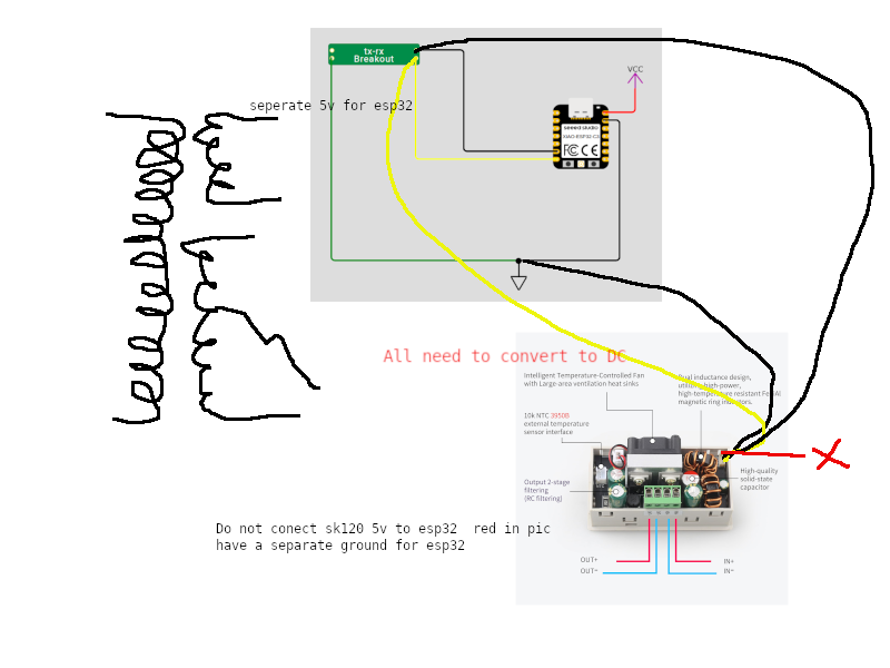
Sketch plus module photos: all transformer feeds must be rectified to DC before IN+/IN− on each XY-SK120X. The ESP32 connects to the module’s serial through a TX/RX breakout. Do not tie the converter’s 5V rail to the ESP32—run a separate 5V (e.g. LM7805) for logic and keep ground planning explicit.
Simple rectifier boards (bridge, cap, bleeder)
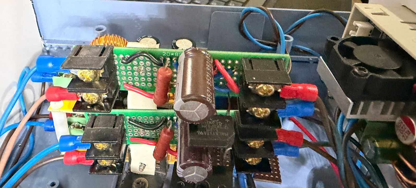
Each rail is a plain AC → DC stage: bridge rectifier, bulk capacitor, and a bleeding resistor across the cap so stored energy does not linger forever after power-down. Screw terminals and crimped leads keep the high-current path maintainable.
Mid-assembly in the top box
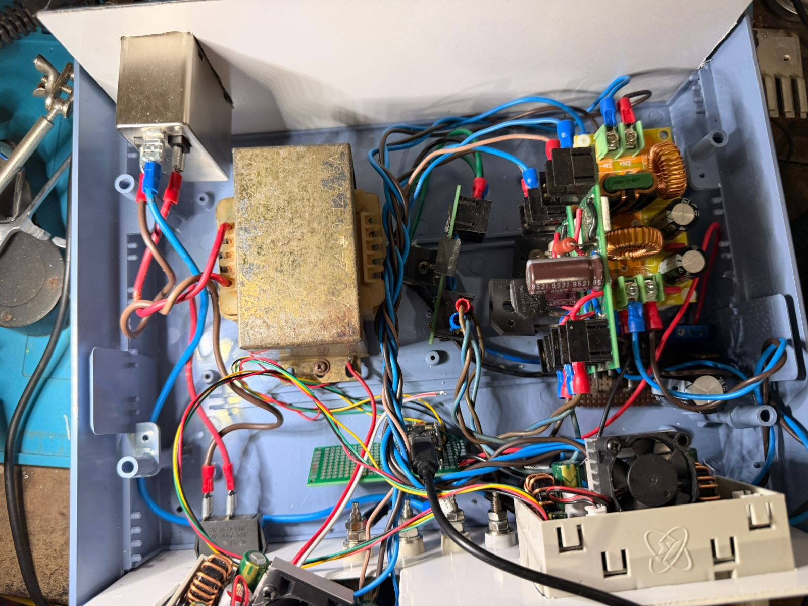
Halfway there: multi-tap transformer, AC line filter, ESP32 Super Mini on perfboard with USB out for the PC, toroidal chokes and caps where the design calls for them, and both SK120X modules aimed at the front panel—enough copper spaghetti to justify the smaller MCU board.
Experimenting with Modbus
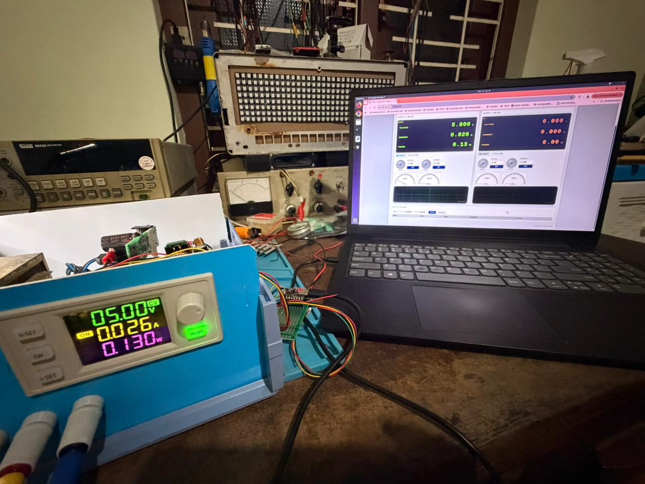
First end-to-end check: Modbus through the bridge, front-panel readings vs scripted/GUI values. Once STATUS and writes lined up with the module LCD, the mechanical closure was allowed to continue.
Finished unit
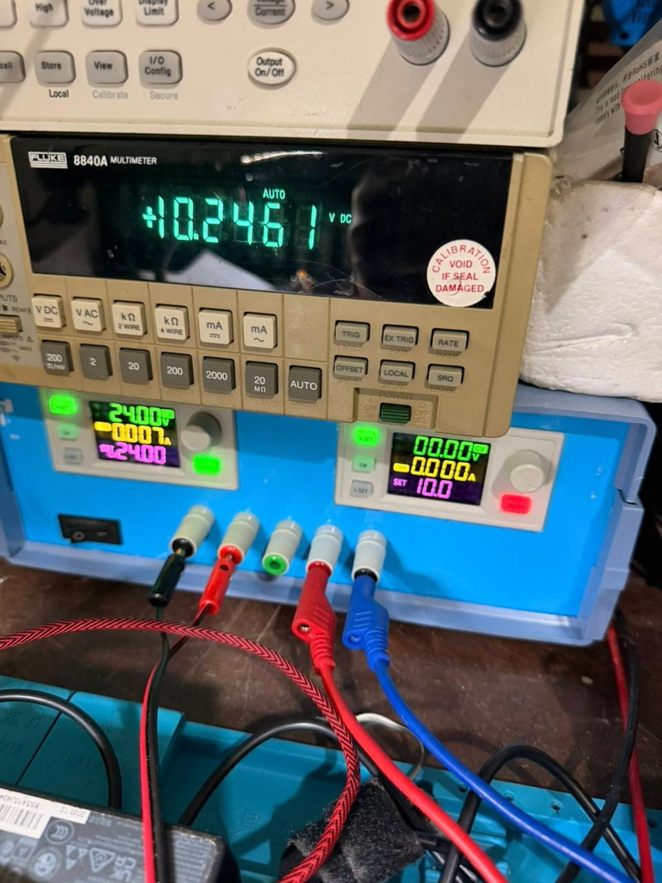
Done enough to use: two channels in one blue case, outputs on binding posts, verification with a 6½-digit DMM when it matters. Not a cal-lab traceable reference—good enough for day-to-day bring-up.
Linux GUI (psu-gui)
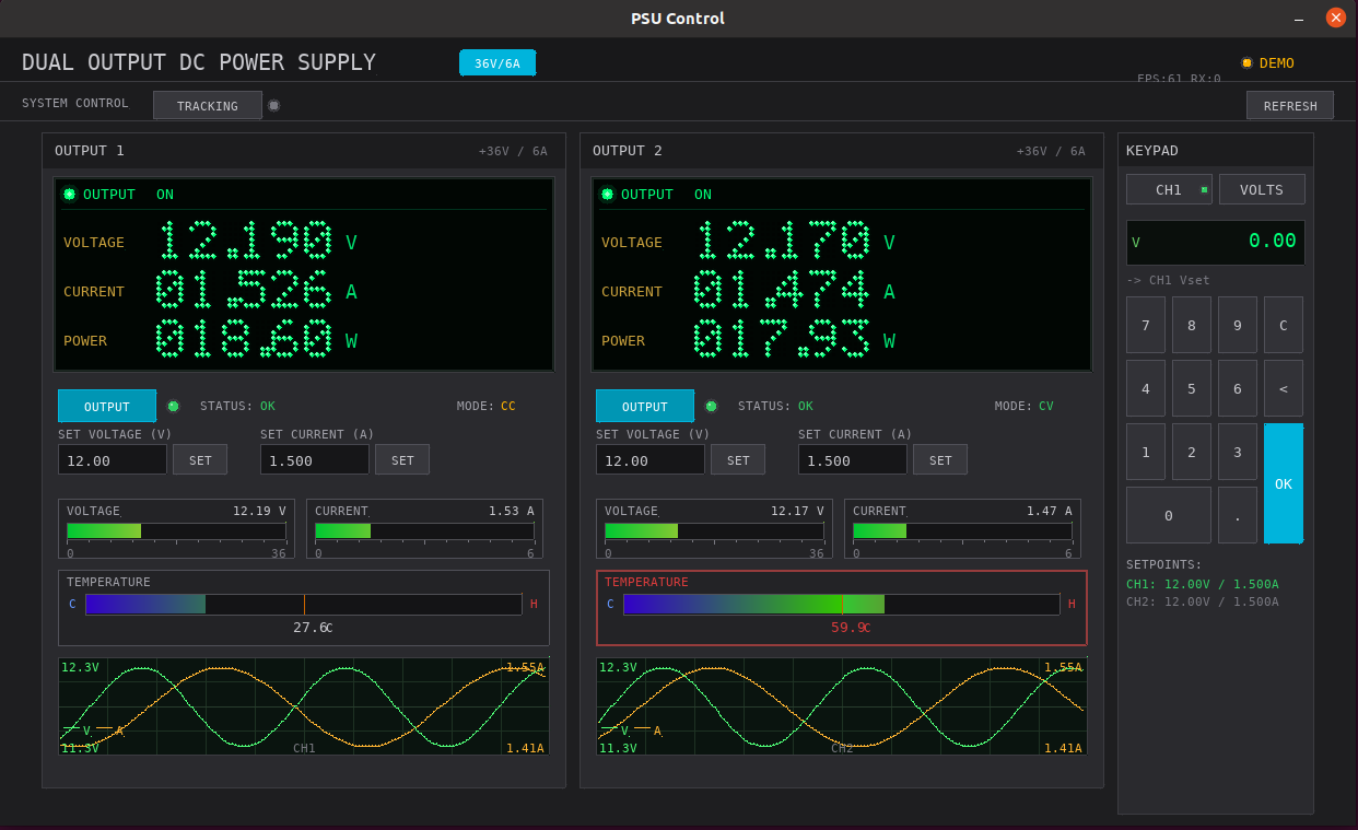
Current SDL2 interface built and run on Linux: dual readouts, CC/CV indication, temperature, mini scope panes, and the shared keypad. Still subject to the usual serial + Modbus delay—fine for tuning; use raw serial when you need minimum latency.
Parts List (With AliExpress Search Links)
Use these as starting searches—pick sellers with good feedback and matching voltage/current ratings for your mains region.
| Item | Note | AliExpress (wholesale search) |
|---|---|---|
| XY-SK120X / SK120X buck-boost module | Quantity: 2 (one per channel) | Search: XY SK120X |
| ESP32 “super mini” or compact module | Space-saving; devkit if you have room | Search: ESP32 super mini |
| RS-485 transceiver board (MAX485-class) | Half-duplex, DE/RE as per firmware/HAL | Search: MAX485 module |
| Bridge rectifier (current for your transformer) | 3× as in this build’s architecture | Search: bridge rectifier 35A |
| LM7805 + heatsink if needed | 5 V linear reg for logic | Search: LM7805 TO-220 |
| Capacitors, resistors, connectors, fuse, wiring | Class X/Y caps, DC link caps per your rails | Search: electrolytic capacitor kit |
| AC line filter / common-mode choke (optional but useful) | Helps conducted noise; won’t fix everything | Search: AC line filter EMI |
| Enclosure, standoffs, thermal paste, isolation | Treat mains as lethal | Search: aluminum project box |
Transformer: this write-up assumes a salvaged or second-hand multi-tapped transformer (e.g. 24 V–0–24 V and 0–12 V windings). If you buy new, match secondary voltages and VA to your rectifiers and module input limits—do not copy random numbers from a blog without checking datasheets and fuse ratings.
Firmware, Serial Protocol, and GUI
- Repository: espmodbus @
experiment— serial text commands (READ,WRITE,STATUS,LINK, etc.), 115200 baud, Modbus to the two slaves. - PC GUI (
psu-gui): dual readouts, keypad, scope-style traces—documented in the repo README.
Honest limitations (read before you blame the tool):
- Small lag in the GUI — serial round-trips, Modbus timing, and SDL refresh mean the interface is not a 1:1 substitute for a lab-grade front panel. For automation, prefer scripts talking raw serial.
psu-guiis built and tested on Linux — dependencies are typicallibsdl2-dev,libsdl2-ttf-dev. There is no fully maintained Windows build path from this desk; if you need Windows, plan to adjust the build yourself or use WSL2 / a Linux VM for the GUI.- Safety and calibration — this is DIY. You own isolation, earthing, fusing, and verification with a DMM and scope.
Ripple, Ringing, and “Good Enough” Output
Switching converters always have residual ripple; layout and long leads can add ringing at transitions. I tried line-side filtering and basic output cleanup; results improved but did not vanish. If you live for magnetics and snubbers, this project is a great place to contribute: better input caps, shielding, separate analog ground strategy, or documented scope shots before/after—pull requests and hardware notes are welcome in the repo above.
Why ESP32 “Super Mini” vs a Full Dev Board
A full ESP32 dev board gives more GPIO flexibility and dual-core breathing room—nice when you are parsing USB traffic and bit-banging RS-485 timing. I used a compact module because enclosure space ran out. If you duplicate the build, prefer the devkit unless you are as stubborn about volume as I am.
Encouragement (The Useful Kind)
You do not need anyone’s permission to breadboard ugly, script tests, and iterate. Clone the firmware, change the baud rate if you must, add a third channel in software-only dreams, or fix the GUI lag for your machine—then publish the diff. The bench belongs to people who build, not to spec sheets framed on the wall.
Next step: open espmodbus on GitHub, read the README, wire RS-485 once, run STATUS 1 from a serial terminal, and decide if your transformer still smells like confidence or regret. Either way, you learned something Agilent’s fan was not going to teach you.