Keep Out! Building Your Own Portable L.E.D. Flasher Warning Sign
If you are into home recording, dubbing soundtracks, or theatre production, you know that silence and concentration are essential. Unfortunately, "Murphy’s Law" often dictates that just as you are about to finish a perfect take, someone will walk in with a tray of tea and ruin the moment. Locking the door isn't always the answer, as people may still knock or call out. The solution is a simple, eye-catching L.E.D. Flasher to act as a "Do Not Disturb" sign.
The Circuit Diagram
This project uses a classic astable multivibrator circuit. It is designed to be built with common components often found in a "spares" box.
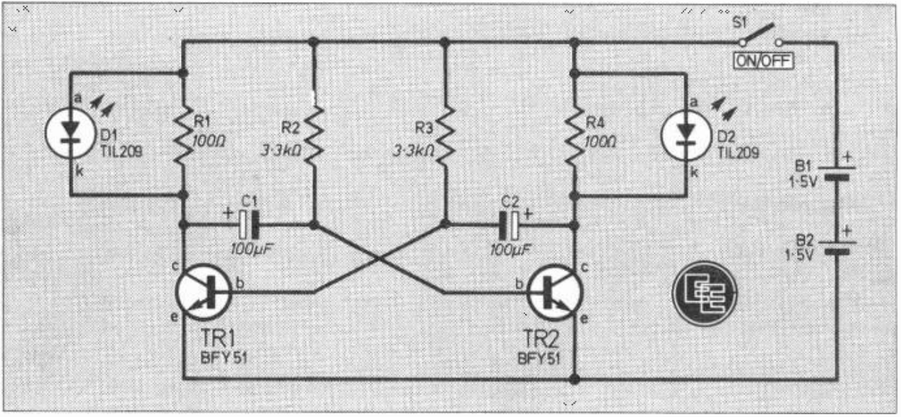
Schematic Breakdown:
- Power: Powered by two 1.5V AA cells (B1 and B2) in series for a 3V supply.
- Switch: A miniature S.P.S.T. toggle switch (S1) controls the power.
- Transistors: Two BFY51 NPN silicon transistors (TR1 and TR2) alternate between "on" and "off" states.
- L.E.D.s: Two TIL209 red L.E.D.s (D1 and D2).
- Resistors: R1 and R4 are 100 ohms; R2 and R3 are 3.3k ohms.
- Capacitors: C1 and C2 are 100µF 3V electrolytic capacitors.
How it Connects:
The transistors are cross-coupled. The positive rail connects to the switch, which leads to the anodes of the L.E.D.s and the timing resistors (R2, R3). The collectors of the transistors are connected to the L.E.D. cathodes via current-limiting resistors (R1, R4). The capacitors (C1, C2) link the collector of one transistor to the base of the other, creating the oscillating flash.
Customising Your Flash Rate
One of the best things about this DIY build is how easy it is to adjust the timing to your preference:
- Standard Flash: Using 3.3k ohm resistors (R2 and R3) provides a flash of about one-third of a second per L.E.D..
- Rapid Flash: Decrease these resistors to around 2k ohms.
- Slow Flash: Increase the values to 4.7k ohms to achieve a rate of about 1Hz (half a second per glow).
- Uneven Flash: If you use different values for R2 and R3, one L.E.D. will stay lit longer than the other.
- Capacitor Flexibility: While 100µF is standard, you can use values like 125µF or 150µF depending on what you have available.
Building and Housing the Unit
The project is built on a small piece of 0.1-inch matrix stripboard (11 strips by 28 holes). A key construction tip is that no breaks are required on the copper side of the board for this specific layout.
For the housing, the prototype used two sections of a Vero General Purpose case (70 x 50 x 40mm) held together securely by nails. The L.E.D.s are positioned to protrude through drilled holes in the top section. Inside, the circuit board is held in place with Blu-Tak, and a piece of paper or foam is sandwiched between the board and the batteries to prevent short circuits.
Portable and Practical
To finish it off, use Letraset (dry transfer lettering) to label your sign with messages like "RECORDING," "MEETING IN PROGRESS," or "DO NOT DISTURB". A coat of clear varnish or lacquer will protect the lettering.
The unit is lightweight and can be easily attached to a door using Blu-Tak or "Buddies". The flashing lights are designed to catch the attention of potential intruders without being overly annoying. Just remember: don't use it too often, or people might start ignoring the warning!.